


Motivation
This winter I had my first Hack Days at FreeAgent. During the Hack Days everybody at FreeAgent teams up for a couple of days and builds something fun and (preferably) useful. That’s when “Machine that goes ‘Ping!’” was born.
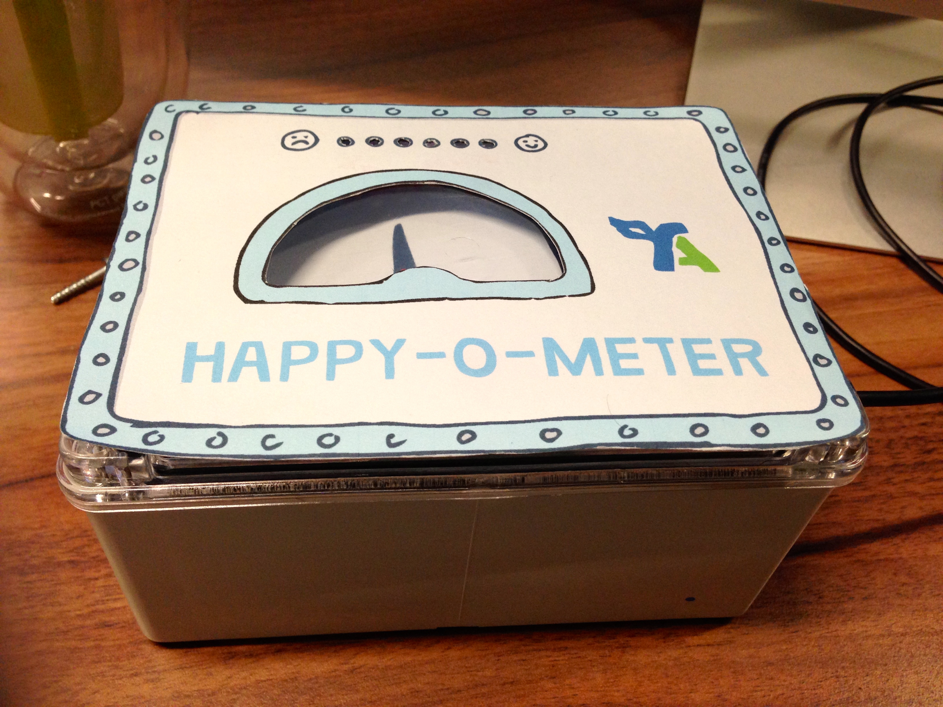
With an Arduino Uno board, some Sugru, bicycle bell, a few LEDs, servo motor and a RabbitMQ subscription to production logs it was able to ring a bell and flash some ligths every time FreeAgent got a new subscriber. The machine was a grand success.
This little project inspired me to do something more challenging. I wanted to further develop the idea of the subsribers counter and I knew that the new version of the machine should not only make a sound when a user subsribes or unsibscribes but also display the total number of subscribers. As an inspiration I used this Geiger counter project I found a while ago. I hadn’t completely figured out the design yet, but decided to use Nixie tubes anyway.
The project
Here’s the impression of what the finished product might look like produced with my rudimentary drawing skills:
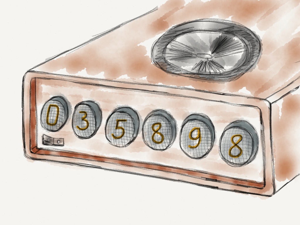
On the inside the architecture is pretty simple: Raspberry Pi gets the total number of subscribers and an event of subscription somewhere online. It sends the number to the Nixie tubes for display and a signal to the speaker on a subscription event.
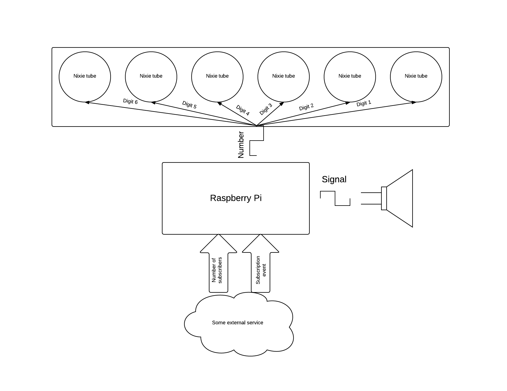
The first part of this scheme I’m going to dive into is the Nixie tubes part.
Nixie tubes
A Nixie tube is a vacuum tube with a bunch of electrodes inside. When current goes through the tube electrodes glow due to the effect called glow discharge.
If you put two electrodes - cathode (-) and anode (+) - in a tube filled with gas, and apply enough voltage, electrons start to “break” from cathode and fly to anode ionizing gas inside the tube and causing a glow.
Nixie tubes have multiple cathodes, shaped like digits from 0 to 9, and one anode. If you connect this common anode to a high-voltage power source and connect one of the digit cathodes to the ground you’ll see the digit glowing with bright light.
Nixie tubes come in different varieties. I’ve got the model IN-4.
IN-4 tubes have 14 pins: 10 digits-cathodes, an anode (pin 4) and 3 more pins the meaning of which is unknown to me.
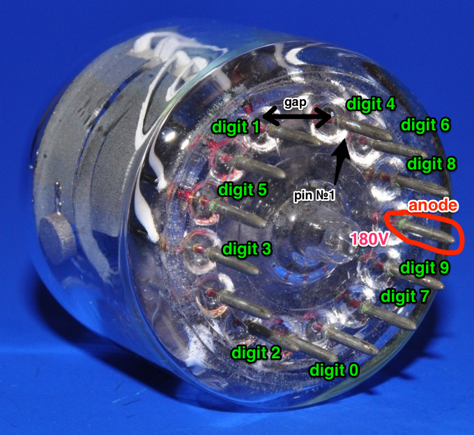 Image courtesy of http://www.tube-tester.com
Because Nixie tubes operate at such high voltage (180V) and because it’s not very handy to look up a pin number you have to “activate” every time you want to display a digit a driver should be placed between a controlling device and a tube.
In this project I used K155ID chip - a high-voltage BCD-to-decimal decoder. More on this in the next post. For now let’s just assume that for each tube we have 4 input pins instead of 10 and if we send a binary coded number from 0 to 9 to these pins the number would show up on a Nixie tube attached to the driver.
Shift registers
To show a 6 digit number, we have to send signals to 6 * 4 = 24 input pins. That’s way too many inputs for a simple device, let’s try to reduce the number.
One way to do this is to align all 24 pins, connect them to a single wire and connect that wire to a Raspberry Pi. Then we can send one signal at a time for each pin on this wire, i.e. form a succession of “messages” like “1 to pin #23”, “0 to pin #22” etc. This process is called multiplexing.
Of course we will need a device that will decide which pin is to receive what signal. For that we can use shift registers.
Serial-in, parallel-out shift register is an electronic device that receives a serial input (a sequence of “1” and “0” send one after another), stores it and transforms it to the parallel output.
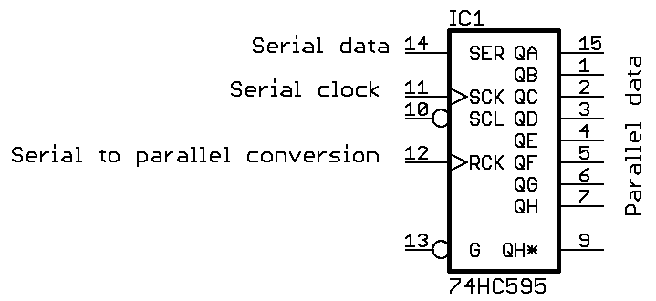 Image courtesy of www.circuitsathome.com
Shift registers have two clock inputs: SHCP or SCK (Shift Register Clock) and STCP or RCK (Storage Register Clock). Every time signal changes from 0 to 1 on SHCP input all data stored in shift register “shifted” one bit to the right. When STCP input is triggered, the data stored in shift the register gets sent to the outputs.
Shift registers can be stacked together, each later one using serial output of the previous one as a serial input. This way the array of shift registers can be used as one big register, allowing to store and convert larger numbers.
As 74HC595 shift registers have 8 outputs we can connect two Nixie tube drivers to each of them.
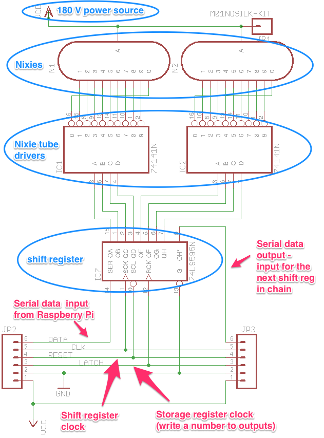
Three boards like this connected one to another can drive 6 Nixie tubes. Elements JP2 and JP3 are sockets containing five wires common to all boards: power (VCC), ground (GND), SHCP (CLK), STCP (LATCH) and RESET (an input signal used to clear a shift register) and serial input and output.
Serial output of the first shift register (QH*) becomes a serial input of the second one while the serial input of the first register (SER) is connected to a Raspberry Pi.
Testing a shift register
To test a shift register on a series of simple inputs we can use an Arduino Uno. We need to plug three inputs of the shift register to Arduino: SHCP and STCP clocks and serial input DS. To monitor the state, we connect 8 LEDs to the outputs.
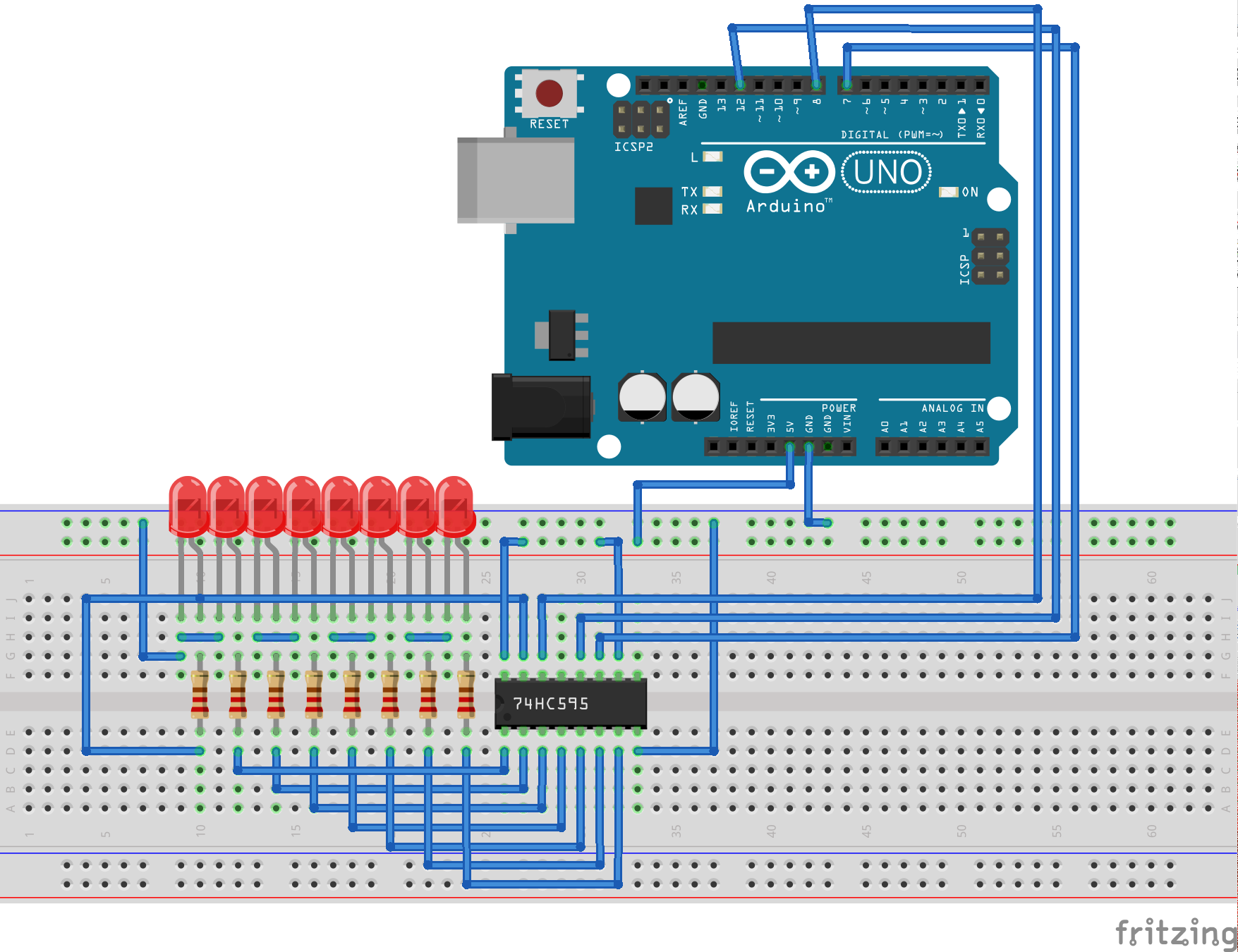
The first test is to send a single 1 to the DS input and “shift” it from the first output pin to the last, blinking the LEDs as the number shifts.
/*
  Testing Shift Register 74HC595N
  Shifting 1 from Q0 to Q7 and over again
 */

int shcp = 7;  // Connect shift register clock input to pin 7
int stcp = 12; // Connect storage register clock input to pin 12
int ds   = 8;  // Connect serial data input to pin 8

int shcp_count = 0; // A counter for the shift register clock
int ds_state = 0;   // Equals to 1 if the Serial Input received 1

// the setup routine runs once when you press reset:
void setup() {
  // initialize the digital pin as an output.
  pinMode(shcp, OUTPUT);
  pinMode(stcp, OUTPUT);
  pinMode(ds, OUTPUT);
}

// the loop routine runs over and over again forever:
void loop() {
  digitalWrite(shcp, !digitalRead(shcp)); // Tick the shift register clock
  shcp_count += 1;

  // Set all variables to the initial state
  // after the sequence is finished
  if (shcp_count == 20) {
    shcp_count = 0;
    ds_state = 0;
  }

  // Let the Shift Register Clock tick once (LOW -> HIGH, HIGH -> LOW)
  // before writing to the serial input;
  if ((shcp_count == 2) && ds_state == 0) {
    digitalWrite(ds, HIGH);
    ds_state = 1;
  } else {
    digitalWrite(ds, LOW);
  }

  // Tick Storage Register Clock if Serial Input received data
  if (ds_state == 1 && shcp_count > 2) {
    digitalWrite(stcp, !digitalRead(stcp));
  }
  delay(500);
}
After uploading this program to the Arduino board you should see 8 LEDs flashing one after another, then the whole sequence repeating.
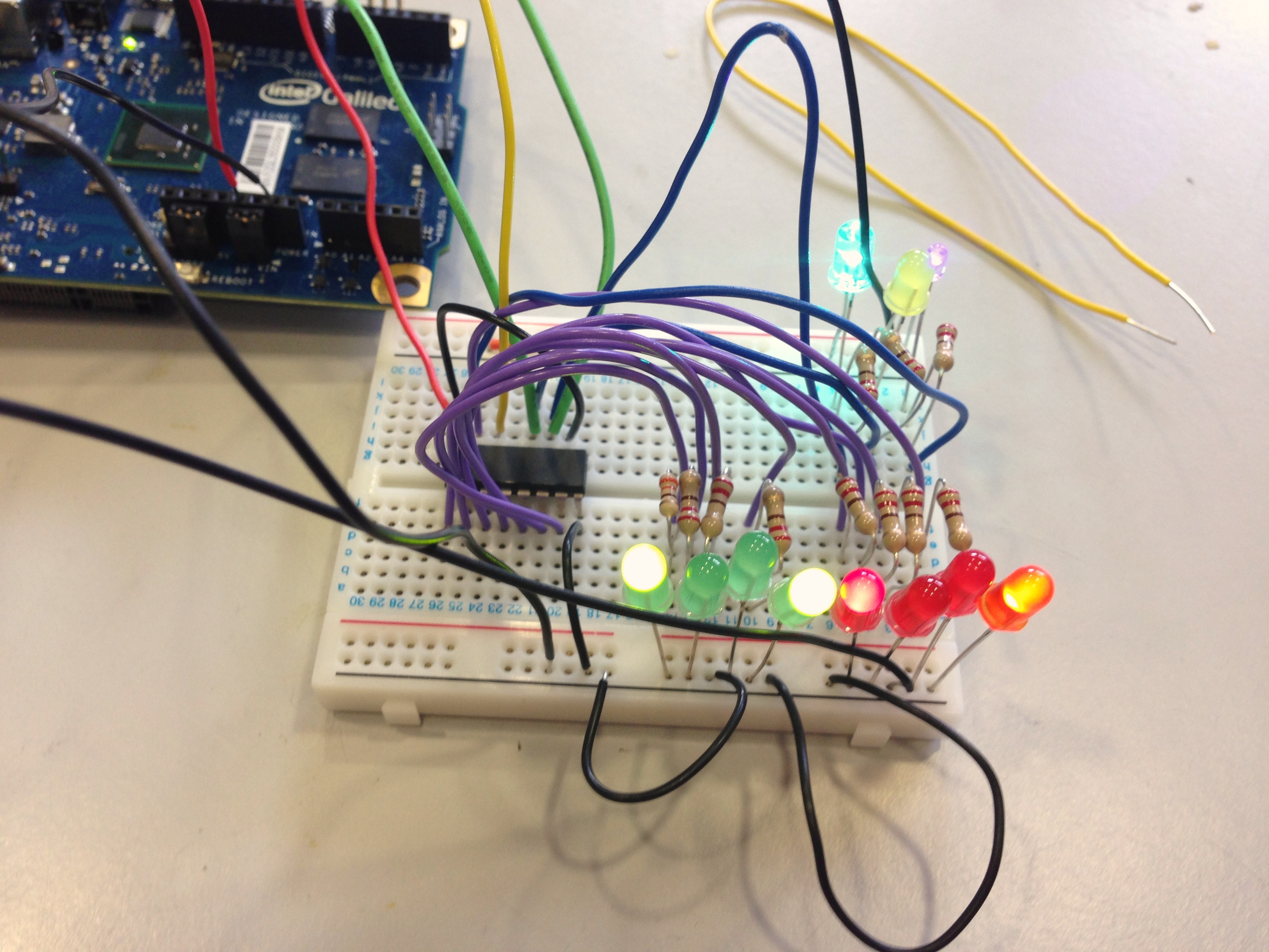
The second sketch features how to write a two-digit Binary Coded Decimal (BCD) to the 8 output pins. The first digit to the first 4 pins and last digit to the last 4 pins. The number in this example is 99. Which is admittedly not a very good example as the number is a palindrome in both decimal and binary bases.
/*
  Testing Shift Register 74HC595N
  Writing two numbers to first 4 outputs and second 4 outputs
 */

int shcp = 7;  // Shift register clock input
int stcp = 12; // Storage register clock input
int ds   = 8;  // Serial data input

int number1 = 9; // Write number 9 to the first 4 outputs
int number2 = 9; // And number 9 to the second 4 outputs
int done = 0;

// the setup routine runs once when you press reset:
void setup() {
  // initialize the digital pin as an output.
  pinMode(shcp, OUTPUT);
  pinMode(stcp, OUTPUT);
  pinMode(ds, OUTPUT);
}

// the loop routine runs over and over again forever:
void loop() {
  digitalWrite(stcp, 0);

  if (done == 0) {
    // At each iteration of this loop the shift register clock ticks once
    // shifting "focus" from one of the 8 outputs to another
    for (int i=7; i>=0; i--) {
      digitalWrite(shcp, 0);
      digitalWrite(ds, 0);

      // Run a bitwise AND on the binary representation of the current output number
      // and the number we want to write to the outputs.
      // Output numbers are in range from 1 to for as we treat first 4 and second 4 separately.
      if ((number1<<4 & (1<<i)) || (number2 & (1<<i))) {
        digitalWrite(ds, 1);
      } else {
        digitalWrite(ds, 0);
      }

      digitalWrite(shcp, 1);
      delay(100);
    }
    done = 1;

    digitalWrite(stcp, 1);
    delay(1000);
  }
}
Here’s the picture where active LEDs form the binary number 10011001 - 99 in BCD form.
Arduino website has a great tutorial on using a shift register with Arduino.
Coming next
That’s it to the shift register! Another chip I used in the project is K155ID1 Nixie tubes driver. In the next post we’ll try to use it to transform an input BCD number to a corresponding pin number on a Nixie tube.